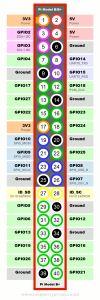
For the sake of simplicity, the Internet connection via Surfstick or WLAN and the power supply were not included in this schematic.
Ports


- A/D converter (HX711) for the load cells:
- VCC at Pin 02/5V (better a 3,3V Pin)
- GND at Pin 06/Ground
- DT at Pin 29/GPIO5
- SCK at Pin 31/GPIO6
- Breeding chamber temperature sensors (DS18B20):
- Pin 17/3.3V
- Pin 14/Ground
- GPIO11
- Temperature, humidity, air pressure and air quality (BME680):
- VCC at Pin 04/5V
- GND at Pin 09/Ground
- SCK at Pin 05/SCL
- SDI at Pin 03/SDA
- Button for switching between maintenance and measuring mode:
- Pin 01/3.3V
- GPIO16
➡ to the shopping list of the used components
In the schematic above not all sensors supported by us are shown, because various sensors can be connected flexibly.
- Temperature and humidity (DHT11/DHT22):
- Pin 17/3.3V
- Pin 14/Ground
- arbitrary free GPIO (z.B. GPIO9)
- Status display (LED):
- Pin 40/GPIO21
- Pin 30/GND
Other supported sensors:
- BME280 (Temperature + Humidity + Air Pressure)
- MAX6675 and MAX31855 ( Temperature)
- PCF8591 (battery voltage measurement) [from version v1.0]
Translated 28.07.2019 by JK

