Power supply via 230V:
The simplest and cheapest solution <10€; material for this usually already available at home:
Idea for power supply in the outdoor area when 230V is available:
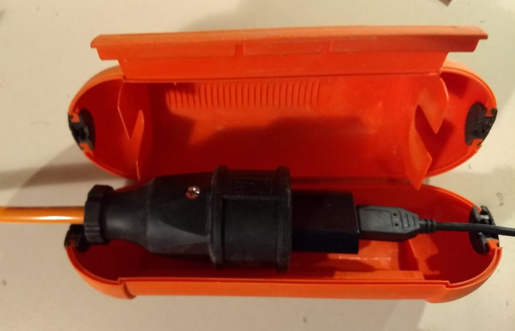
Needed:
- Extension cable outdoor, price depending on length e.g. 10m 10€
- Waterproof box: Richelt in red for 1,65€ or better quality in yellow for 4,50€
- Mini-USB charger with straight plug outlet, 4,60€
1000mA type are good enough for a Pi-Zero (mine need max 250mA).
Here are some Reichelt order numbers:
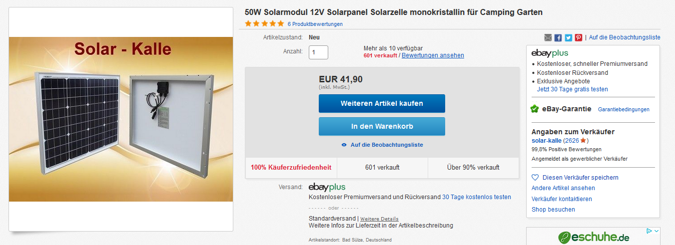
Power supply via solar cell:
670 mm x 550 mm x 35 mm, 6kg with MC4 connectors.
Was delivered within 2 days!
For the connection to the controller I also used the matching MC4 plug and a rest real (4mm²) PV cable.
I bought these MC4 plugs (I also need the rest for another project).
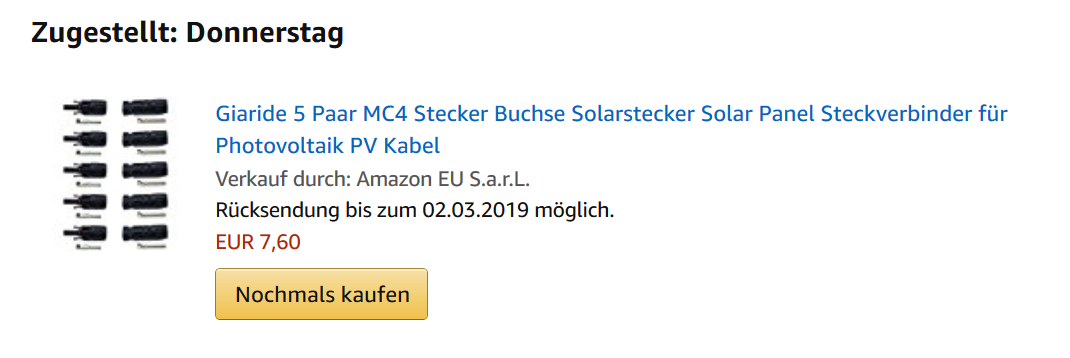
Since I don’t have a suitable crimping pliers, I simply pressed them together with a Komi pliers in the crimping area and then soldered the connection, with the few milliamperes that tile here this is always good.
For the processing of these connectors there are also lots of videos, e.g. this one.
To make the plug waterproof it needs a suitable cable, so it is best to use the original UV-resistant PV cable and not a normal 4mm² (PVC) cable.
The PV cable has a much thicker insulation/outer diameter.
Even if the controller does not look like this, the thickly insulated PV cable fits in without a problem. There are often short solar cable remainders free of charge with local garbage collection places or times with ebay classified advertisements to look, something like that remains with each tidy PV installation. When pulling in the string lines (e.g. from the roof to the inverter in the basement) you always prefer to leave the cables 2m longer than 10cm too short and that will then be cut off and thrown away.
When connecting the cables to the controller, observe the polarity (cable ends on the module are labelled).
PV-Regler
20A Solarladegerät für 12V-Batterie mit LCD Display und USB-Buchse:
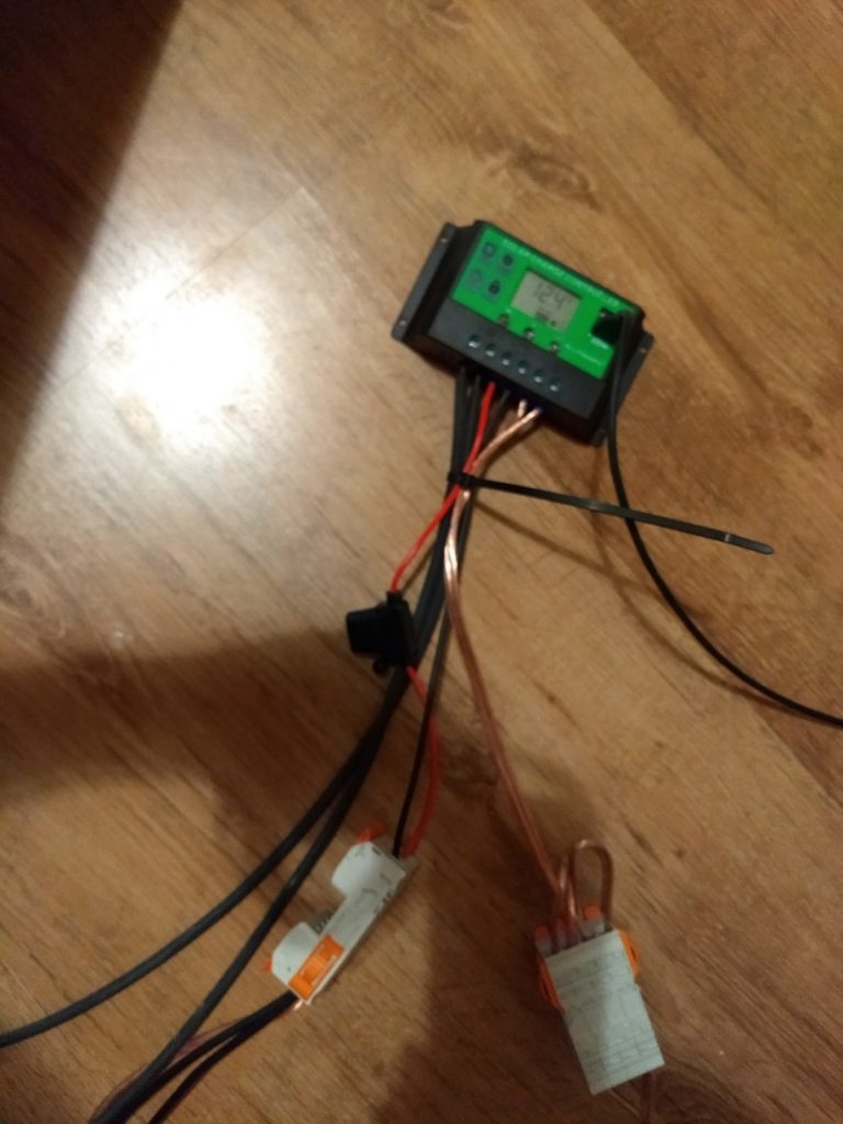
20A solar charger for 12V battery with LCD display and USB socket:
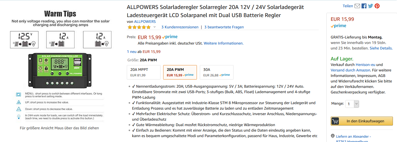
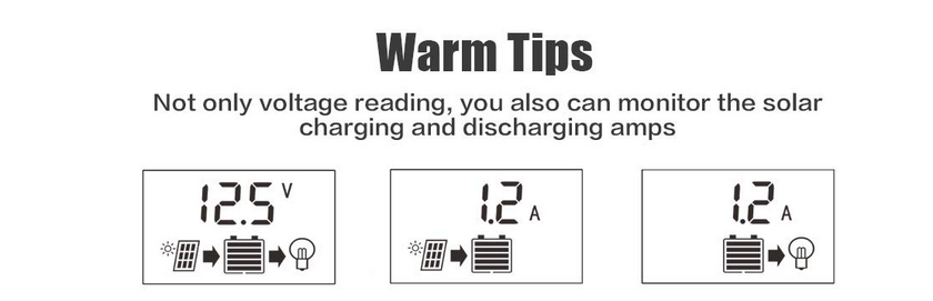
Displays charge & discharge current and battery and PV voltage and battery level.
Towards the battery I installed a waterproof 12V fuse holder, (for normal KFZ(ATO) fuses (fuses were included).
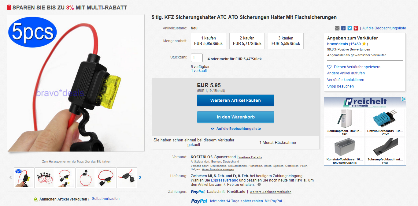
The controller also has some built-in overload protection, but I don’t trust it that much.
What happens if you short-circuit a 12V cable that is connected to a car battery without security (and there is dry grass on the outside…) can be imagined by everyone. I give only one keyword: welding machine…
PV underframe completely assembled
Consisting of
- 2x hinges
- 2x gate hinge
- multiplex board
All these parts best to buy locally in the cheap building market (online is usually more expensive).
In the cheap building market there are the screws also individually to the kilo price.
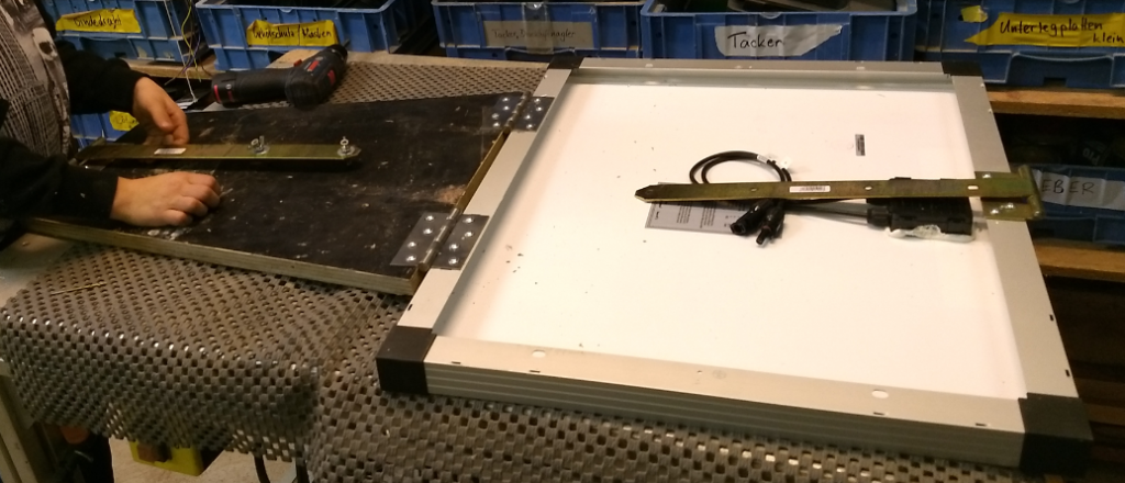
Module mounted on aluminium frame with 2 hinges on Multiplex rest plate (with self-tapping screws without pre-drilling directly into the aluminium/wood).
I marked the positions of the holes with Edding before.
=> Then you see immediately if something shifts when screwing on.
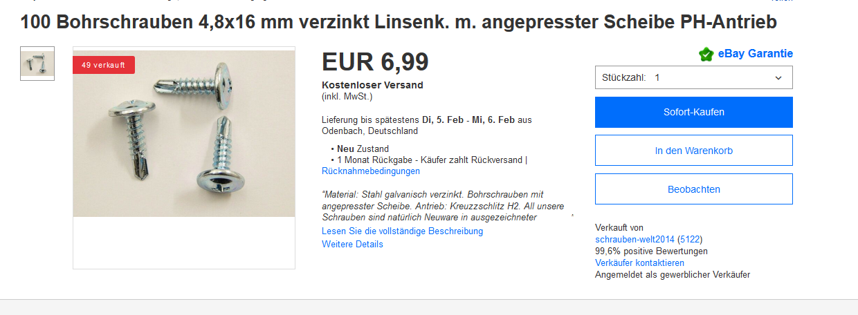
Self-tapping tapping screws with drill point:
When screwing on, make sure that the two axes of the hinge are aligned (longitudinally aligned), otherwise it will jam later!
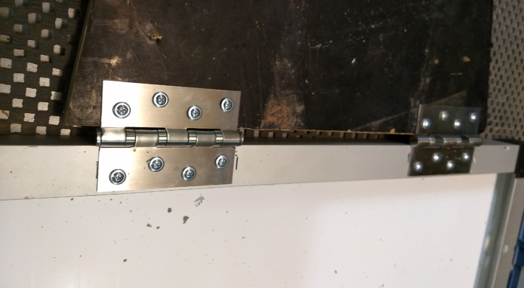
2x gate hinge for variable installation angles, screw on centrally.
=> The installation angle can also be folded flat between the module and the Multiplex panel to save space, e.g. for storage.
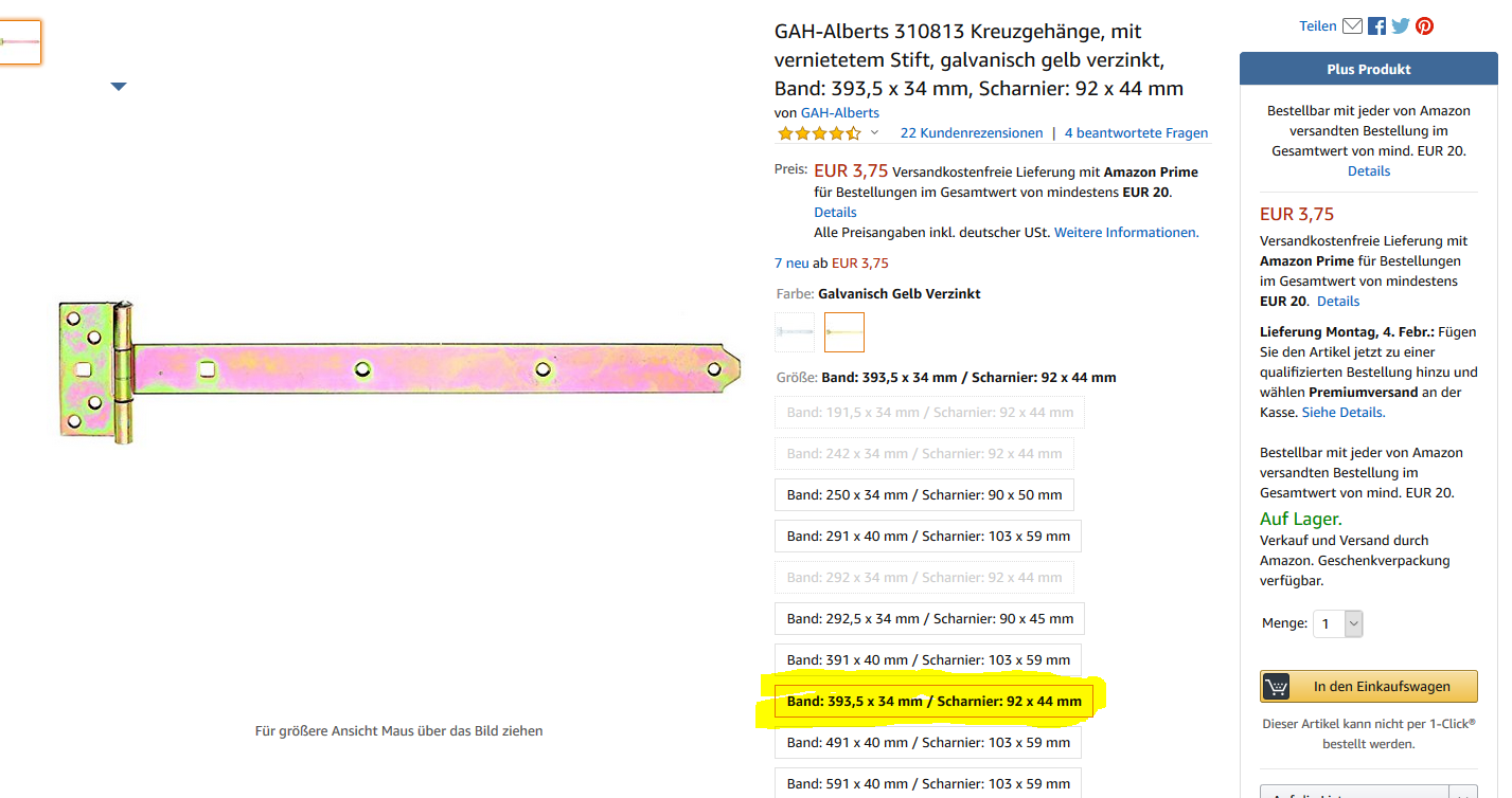
With other hinge types, make sure that the drill holes on the long side (hinge side) are equidistant, then any tilt angle can be set later.
Also make sure that the hinge side is not wider than here (44mm), otherwise the holes will reach into the empty space. And I wanted to have as many screws as possible on the thin module aluminium frame so that it would last in the long term even in strong winds.
2x hinge 100×75 (stainless steel) can also be galvanized.
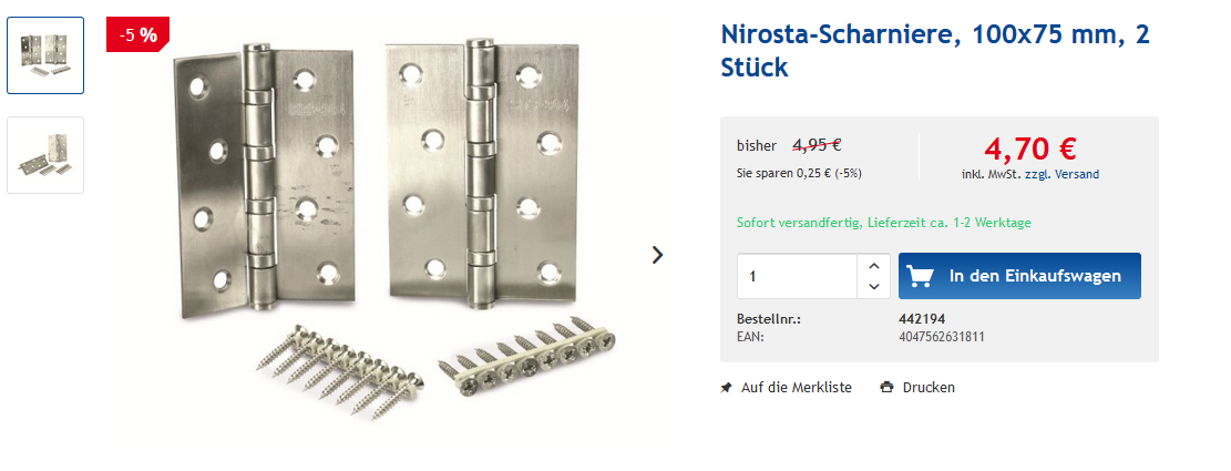
If the type is different, make sure that the drill holes are staggered so that the protruding screw heads do not collide when the screws are folded up, this fits the type shown above. The supplied screws should be thrown into a waste box or rubbish, they will not help us (they are also too long for 22mm multiplex).
When screwing on, make sure that the two axes of the two hinges are aligned, otherwise it will jam later!
Multiplex board
(screen printing plate) Dimensions 54×42 cm (min. 18mm thick).
In a DIY store you can buy the cut for expensive money or at a construction site where concreting takes place, ask if you can take a small piece with you from the garbage container and then cut it yourself (but first remove the concrete remains, the saw blade thanks it).
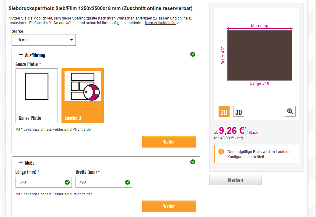
Dimensions can also deviate; see trapezoidal part at my place…
The two hinges should not sit too close together, otherwise it becomes too wobbly.
The tilt angle can be adjusted without tools with two times two wing screws.

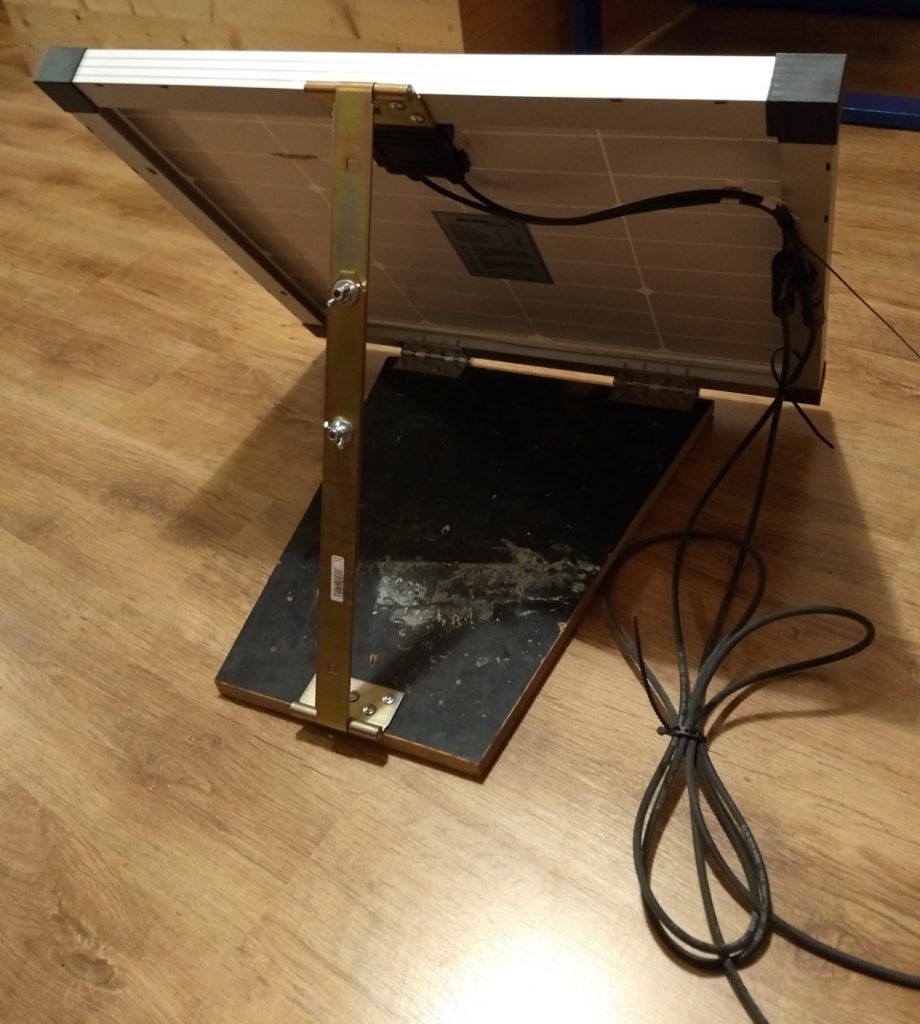
The PV cable is still tied to the holes in the frame with cable ties, so that in the wind the cable does not shy away from the back of the module (on the back is only an EVA film laminated on; if there is a crack in this film and it penetrates (air) moisture to the PV cells then it was that with the module in no time…)
The whole movement is now glued onto a bee hive sheet metal lid with silicone, which is then glued onto a wood (OSB) inner lid.
Inside the “empty” box comes the battery and the charge regulator.
The whole thing is then later fastened to a pallet with a tension strap.
- Silicone lumps applied to wooden inner lid
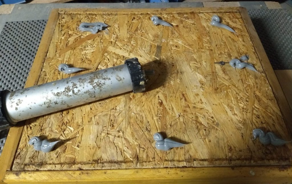
2. sheet metal cover put on/glued on (not screwed, we don’t want any holes in the sheet metal)
3. Silicone again on the sheet metal lid
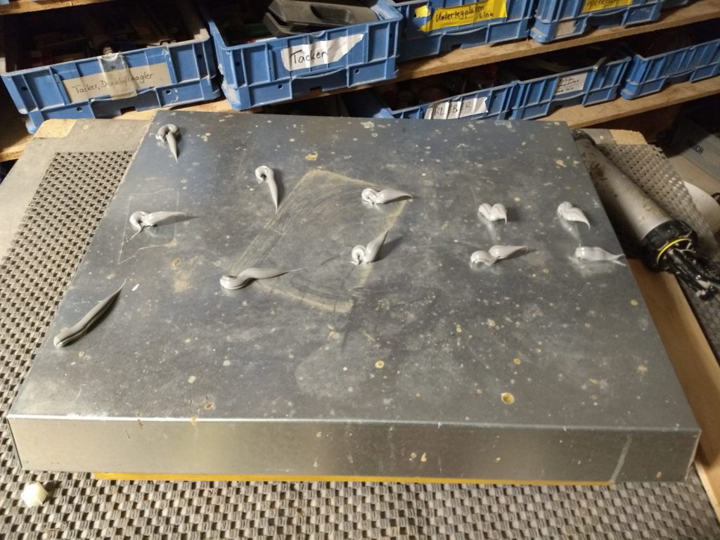
4. PV module holder glued on
Allow to harden for at least 1 day (do not move).
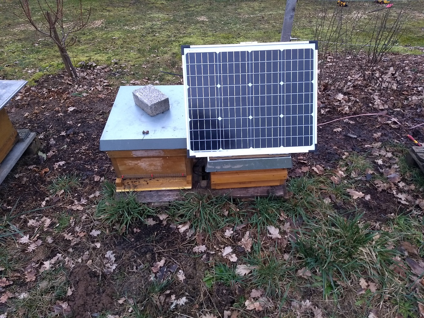
Outdoor installation:
Thread the battery on the pallet before tightening the strap under the pallet.
The (fused) 12V cable that goes to the floor scale is also threaded under the pallet. On the way to the next prey it has to be buried a bit to protect it from lawn mowers and the like. In contrast to a 230V cable, however, no 60cm earth cover is necessary; if anything breaks, there are no dangerous voltages and with the 10A fuse nothing ignites so quickly.
With my shoe the 12V cable comes out again and goes to the next floor scale.
Another full frame (or two half frames) on top and the battery house is finished.
The MC4 connectors are connected to the solar panel and secured with cable ties.
Another manual shaking test: Now a storm can come.
From the front:
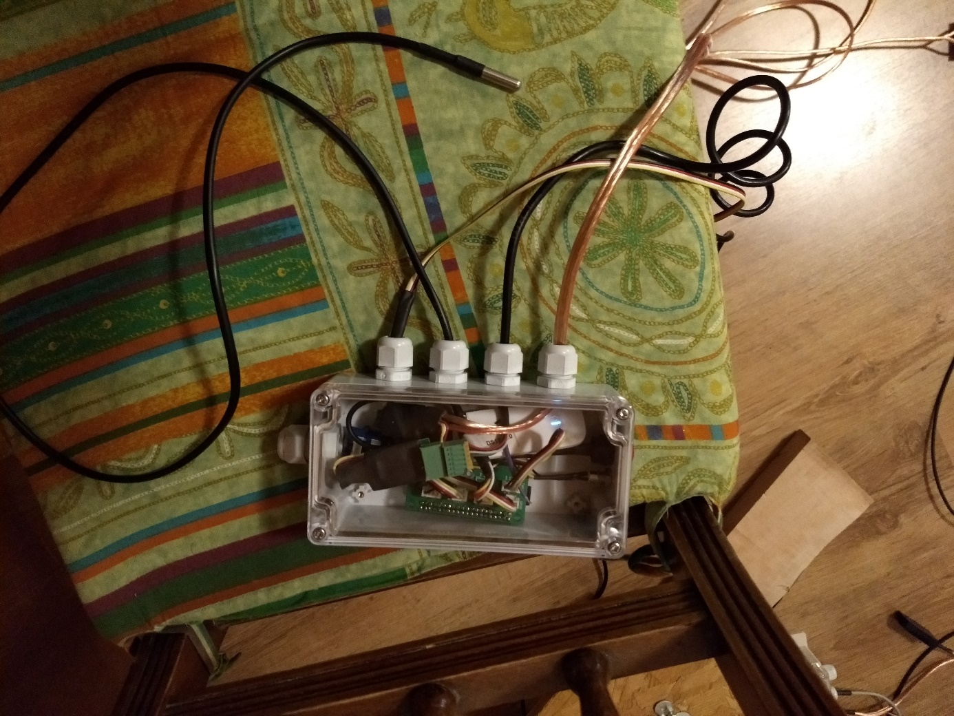
The 12V cable from the battery to the floor scale (which still has to be buried) is not connected directly to the next floor scale but via a normal rubber distribution box with two pieces of 3-pole wago terminals with lever operation for flexible cables up to 2.5mm².
Via the unused hole in the junction box, in which the screwdriver is currently inserted, the cable can then go on to the next floor scale.
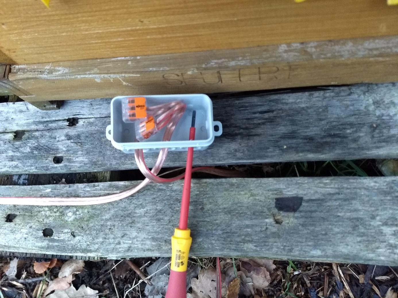
If something needs to be repaired or changed on the floor scale, the cable can simply be disconnected via the lever operation without affecting the rest of the installation.
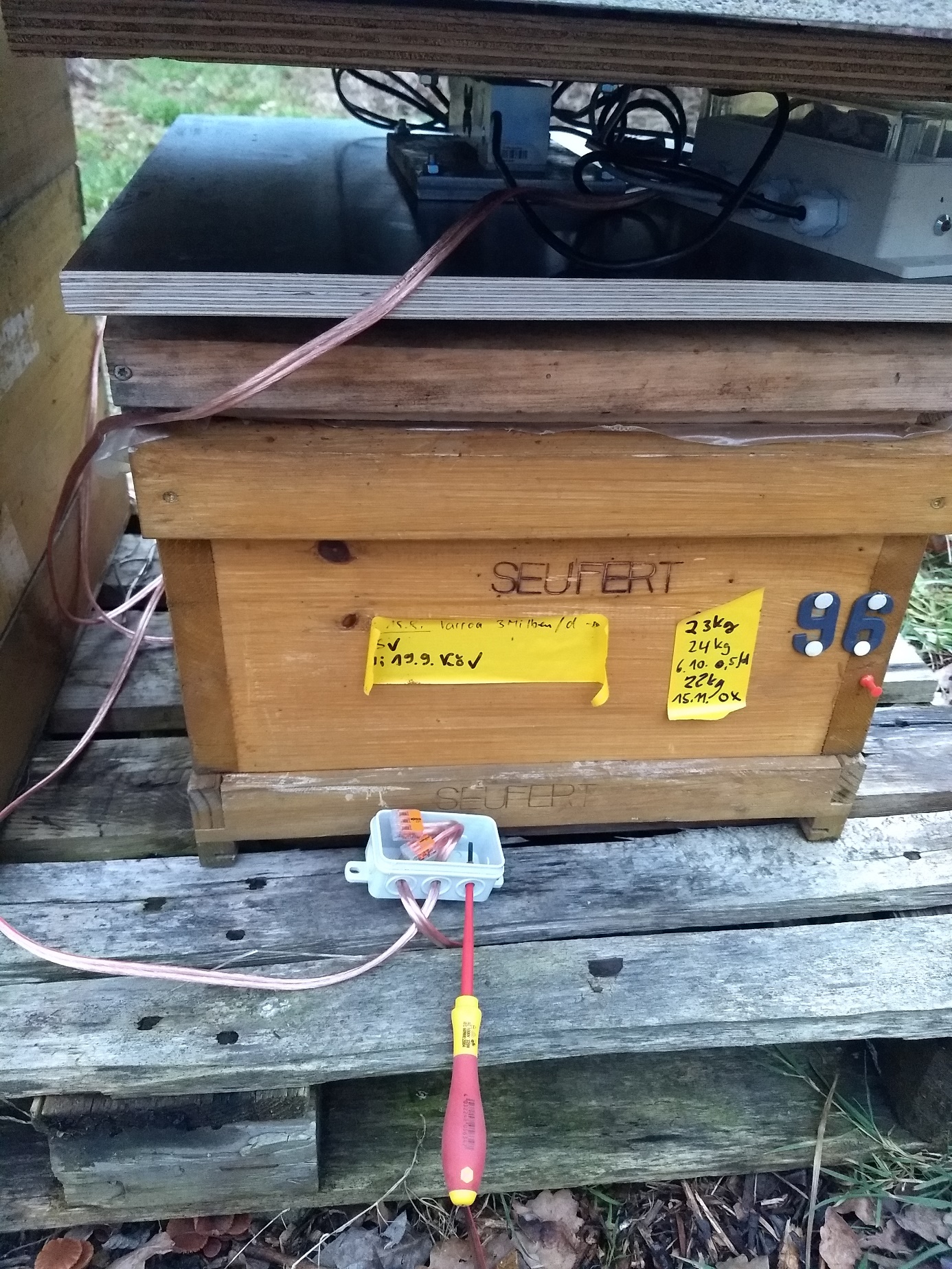
Here in the experimental setup the (not yet completely finished) stick scale still stands on the loot (makes no sense so of course), I did not want to disturb the bees in winter unnecessarily (must still install the stop buffers and firmware update is still necessary). But I wanted to see how the stick scale behaves when the weather changes… It’s still an experimental stage.
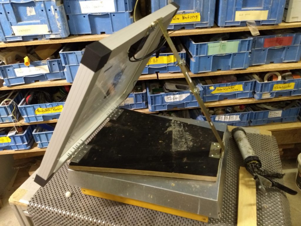
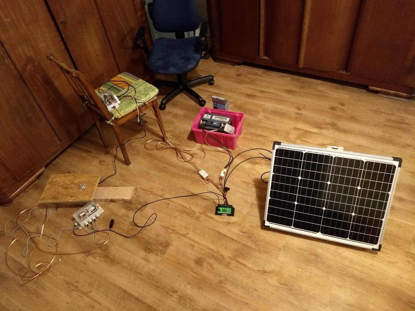
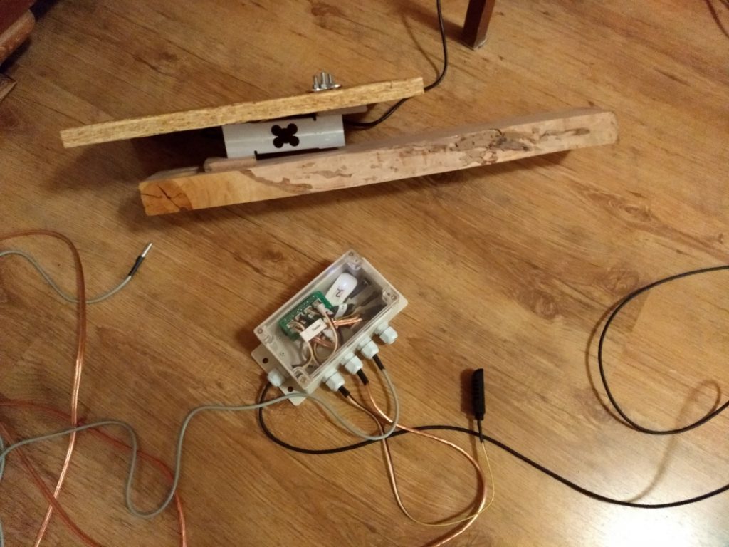
Indoor test setup
With solar cell and charge controller and battery (of course the solar cell does not work in the room…).
Translated 19.10.2019 by JK

Hi Alexander,
vielen dank für die hilfreiche Anleitung!
2 Fragen:
1.Kann ich auch einen 10A Laderegler nehmen?
2. wie hast du die 12V Leitungen an der Beute dann an dein Rasp angeschlossen? welchen Wandler oä brauche ich?
Grüße
Kevin
1. reicht sicherlich.. habe ich nur nie getestet der Typ von mir läuft jetz 2 stück 2 Jahre problemfrei..
2. einen 12V auf usb Wandler siehe https://honey-pi.de/einkaufsliste/ Unterpunkt Strom: