Here I have chosen the following structure:
- One screen printing plate each at the top and bottom.
- It is screwed onto a 100x200x10mm steel or aluminium plate for load distribution.
- Between the load distribution plates there is a spacer plate on each side which is adapted to the bore pattern of the load cell.
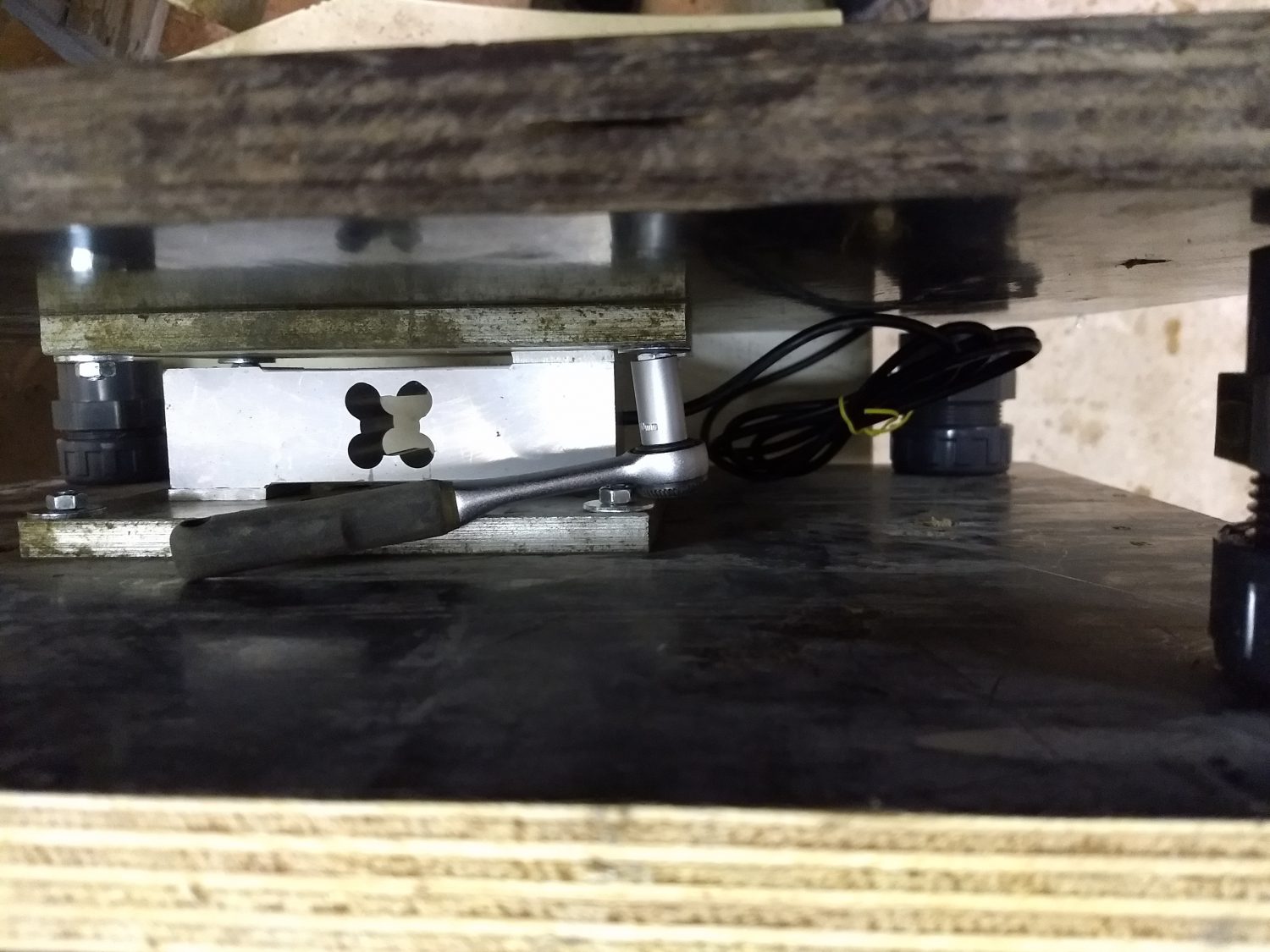
- At each of the four corners there is an (adjustable) deflection limiter.
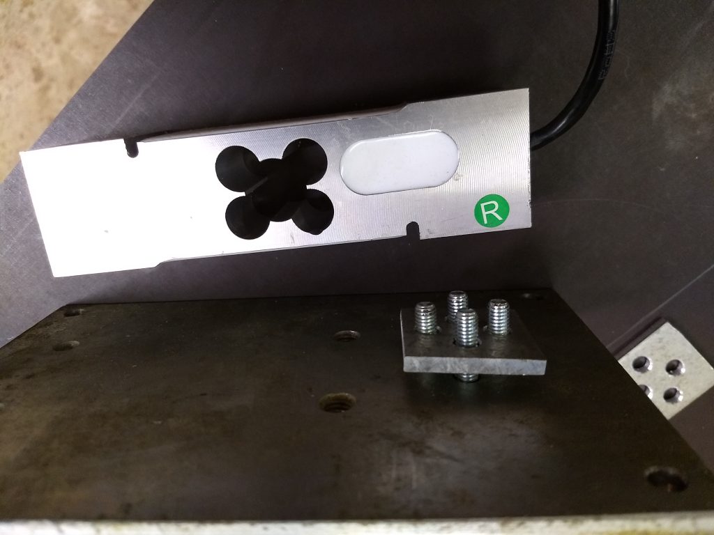
- And in the middle comes the most important one: The load cell (type Bosche H30A or identical) with a weighing range of 150kg or 200kg.
The scale frame itself offers plenty of scope in terms of price. The cheapest solution consists of used Betoplan panels with a Chinese load cell (Amazon 15€) (at taobao 10€) and aluminum & steel plates from scrap for a total of about 20€.
Up to the 4-star version for 100€ with Bosche load cell for 55€, 2 new aluminium plates from ebay (10x100x200mm) – for load distribution (5€ each + shipping), new screen printing plates from the DIY store (2×10€ each), height adjustable 60mm stainless steel deflection limiter. Approx. 10€ and if you really want to make a big deal, you can buy the original distance plates from Bosche for 10€.
Optically there are worlds between both solutions, whether it makes a difference for real operation, time will tell, (have built up both variants (and mixed variants)…)
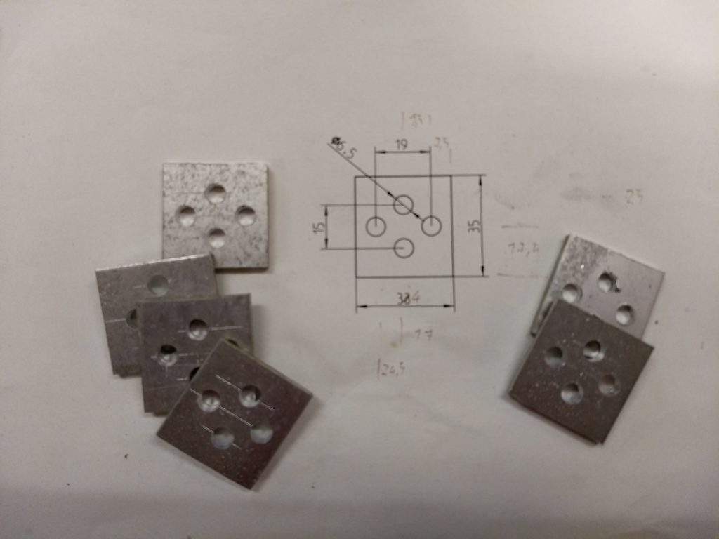
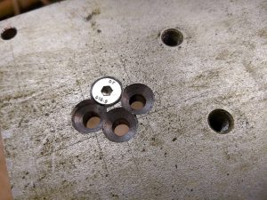
Spacer plate for load cell
From 5mm aluminum remnant self drilled with 6.5mm HSS drill or for a lot of money finished bought at Bosche 2pcs for 10€.
I cut the remaining aluminium pieces on the circular saw with a trapezoid flat tooth saw blade and a lot of care.
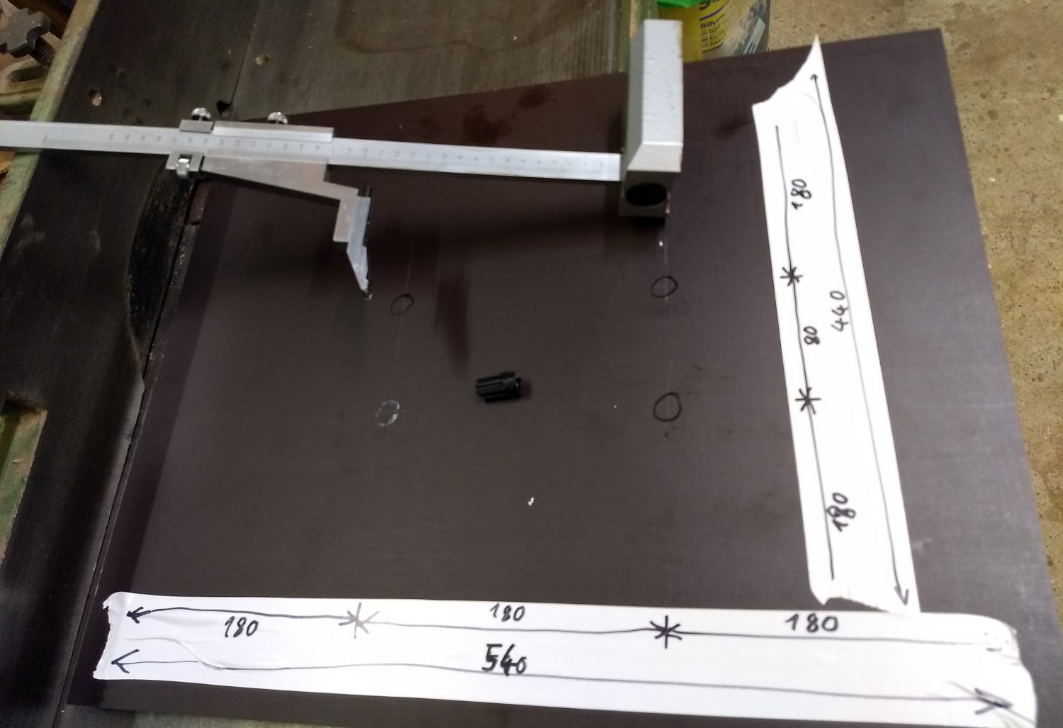
Cover and base plate made of screen printing plates
Bei Neukauf im Baumarkt habe ich mich für das Maß 540x440mm entschieden.
The four holes with which it is screwed to the load distribution plate are 180mm from the edge.
As usual, the holes are drilled again with 6.5mm (best with a wood drill with center point).
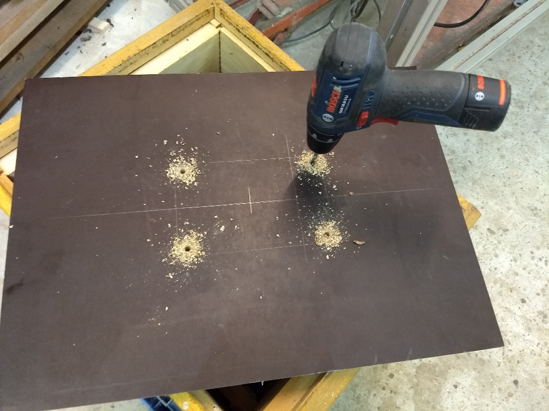
Still chamfer the edges (for the optics).
And from the outside of the screen-printed plates, the 6×40 lock screws can be knocked in with a hammer. For the outside of the scale I chose the corrugated/rough sides of the screen printing plates.
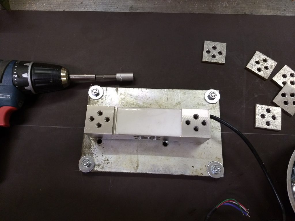
Load distribution plates aluminium 100 x 200 x 10mm
Drilling plan:
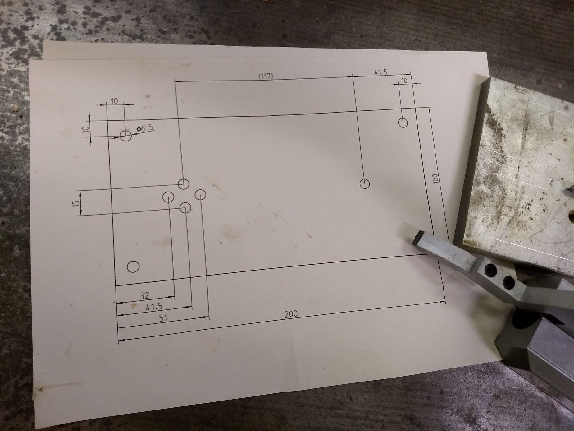
Marking and punching (the two already drilled holes have no meaning, they were already inside the galvanized steel plates of the scrap, but they don’t disturb either).
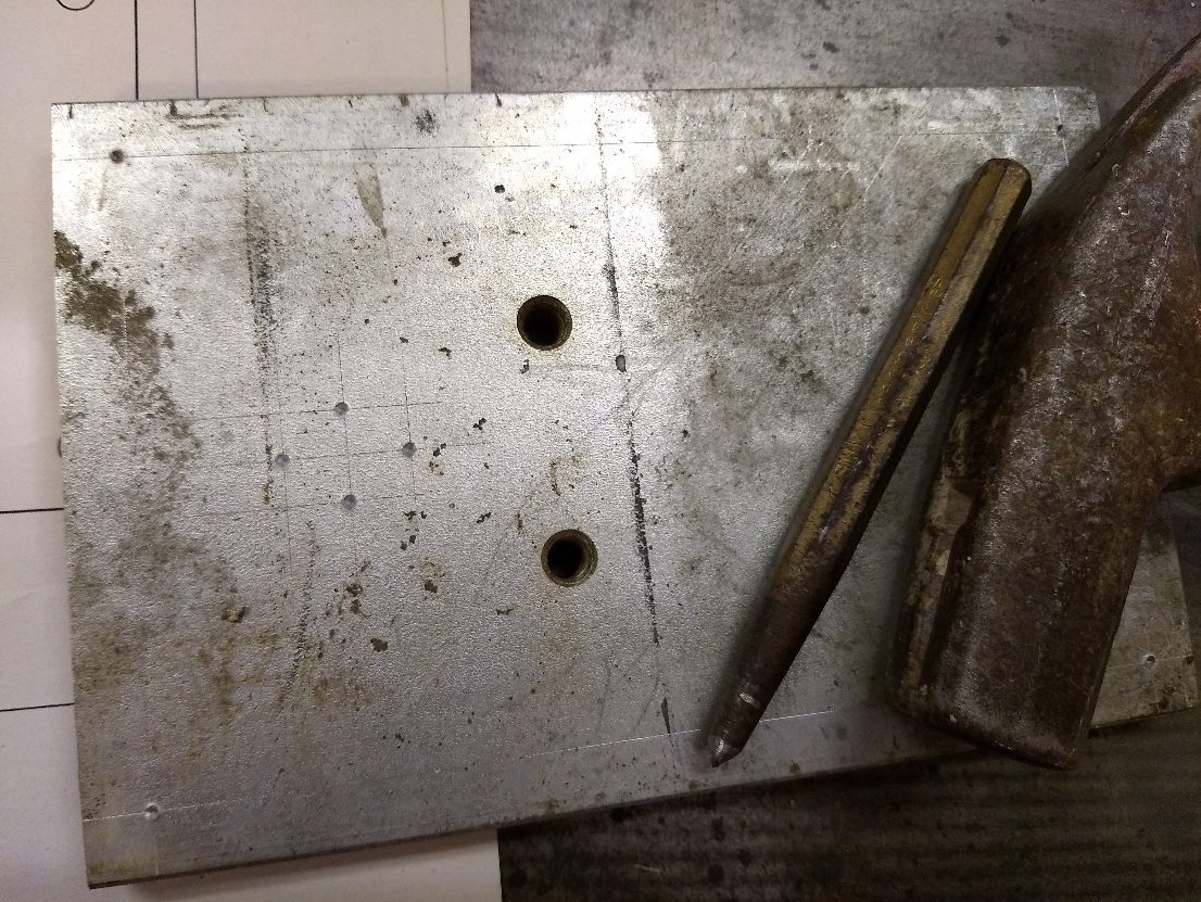
Drill and countersink all 6.5mm diameter holes (so that countersunk screws for load cell mounting no longer project).
Mount load cell with spacer on load distribution plate (with 2x 4 countersunk screws M6x 30).
And on screen printing plate with 4pcs. M6 nuts.
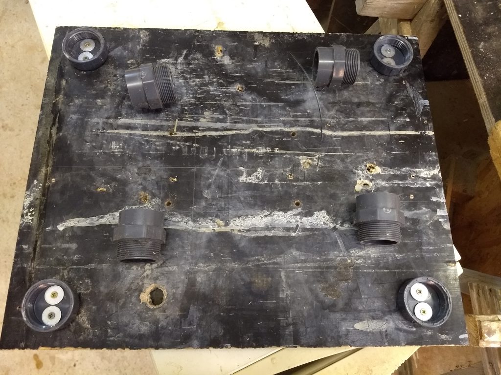
Deflection limiter
In order to avoid destruction of the measuring cell if the load in the corner area is too high and to avoid too strong a wobbling of the prey during wind or working interventions, the deflection at the four corners is limited to approx. 5 mm.
Since the screen printing plates will bend and swell in the course of time and under the influence of weathering, an adjustable deflection limiter is selected here. Does anyone have (long-term) experience with a (non-adjustable) wooden block as a deflection limiter?
Variant 1: 1.5 inch (1 “½”) PVC-tacky
(but which are not glued…); Purchased from PVC-Welt.de:
Cap with internal thread for screwing to the bottom: A-816-50 4pcs. approx. 4,50€
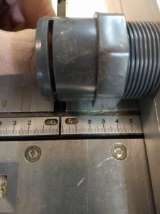
Nipple/transition piece with external thread A-302-40.50 4pcs. approx. 4€.
Other than shown on the following picture, the PVC adapters have to be shortened to 54mm (I do this on the circular saw):
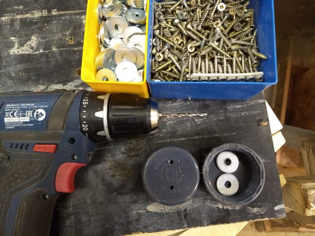
The PCV 1,5″ caps are fixed without gasket with short Spax(4×20) with large M6 washers on the bottom in the four corners (with two screws each).
Pre-drill PVC cover with diameter 4,5mm beforehand.
The spacers are screwed onto the base plate. If they were mounted on the cover, dirt could then collect more easily in the gap between the base and the spacer and lead to a measurement error.
Variant 2: Stainless steel sleeves and caps:
Stainless steel V4A end cap Hexagon external thread 1 1/4″ (EF646) 4pcs 10,70€
Stainless steel V4A sleeve female thread 1 1/4″ (EF106) 4pcs 18,10€
The stainless steel sleeves do not have to be shortened and have an adjustment range from … to …. mm. (and look best of all solutions.)

Varinte 3: Plastic furniture foot 75mm adjustable (4pcs 8€)
They’re too long and have to be sawn off… maybe better:
Plastic furniture foot 55mm adjustable also 4pcs 8€
Variant 4:
Stainless steel furniture foot 60mm 4pcs 10€
Final assembly
Now the lid can be mounted and the scale is ready.
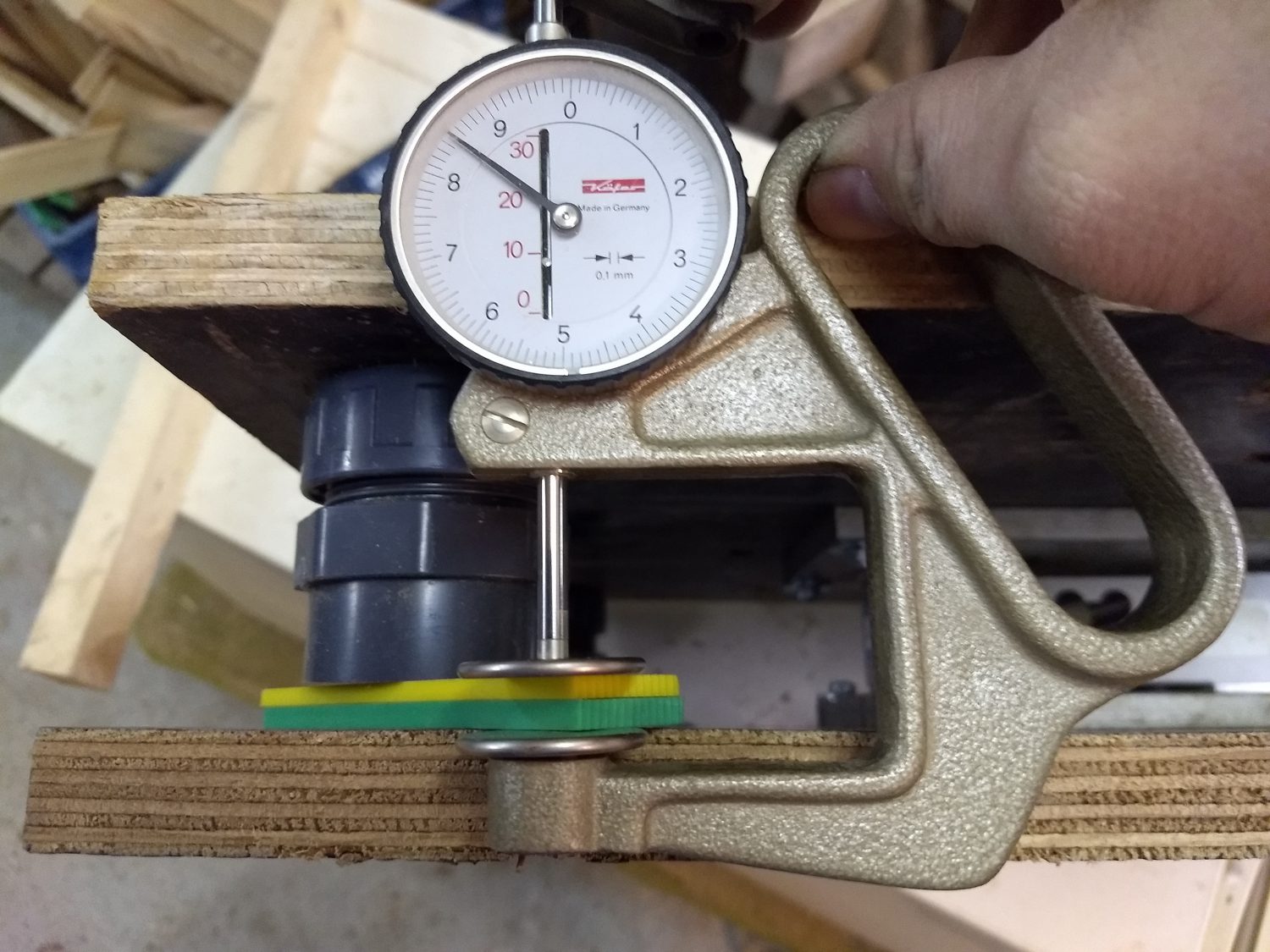
Adjust the spacers:
Start value here is 3mm. Time will show which value is the best in the long run.

With the PVC spacers shortened to 54mm, a maximum distance of 8mm can be set.
Translated 19.10.2019 by JK

Hello,
If by chance someone is having a problem similar to mine I hope this helps.
The weight measurements of my scale had a consistent noise. The values would change from a 5 Kg to a 100 Kg and back to 5 Kg.
After changing the load cell for the German one ( I had the bangood one), the hx711 several times and redoing the wiering I found the culprit.
The wood I was using was an agglomerate 9mm thick. I drilled a squeare to make the screws flush and the thicknes in that part reduced to arround 5 mm. That caused the wood break a little and flex insted of the loadcell inserting the noise in the readings.
Changing for a plywood 18mm thick solved the noise.
I hope this helps someone identify their problem
Hallo,
danke für die super Anleitung. Habe da aber noch eine Frage. Bei meiner Beute (Dadant) ist der Beutenboden offen.
Durch die Siebdruckplatte wäre der Beutenboden nach unten eher verschlossen (bis auf den Abstand von Beutenboden und Siebdruckplatte von der Waage). Wäre das evtl. ein Problem für das Klima im Stock oder hab ich da gerade einen Denkfehler?
Vielen Dank für deine Mühe.
Viele Grüße
Ray
Hallo Johannes
Hallo Javan
Ich hätte eine Bitte. Könntet ihr mir Eure Tel Nr. oder. Mailadresse schicken da ich einige Fragen zu einer Bienenstockwaage hätte. Bin aus Österreich und auch auf WhatsApp App.
Meine Kontakte 0043 664 5201707
oder. [email protected]
Danke im Vorraum
mfj
Hallo! Könnte mir jemand die Stärke der Siebdruckplatten zumailen . Vielen lieben Dank!
Gruß
David Sieglin
ich hab 20mm verwendet
Hi Sven,
ich habe bei mir auch “Abstandshalter” montiert. Ich würde sie allerdings als Ausschlagbegrenzer bezeichnen. Damit kannst du verhindern das sich (je nach Höhe deines Beuten-Aufbaus) die ganze Konstruktion bei Wind aufschaukelt und nur einen maximalen Neigungswinkel erreicht. Passende Öldruckdämpfer habe ich leider noch nicht gefunden.
Außerdem kann man bei einer Stockkontrolle die Abstandshalter fest gegen das Gestell drehen und ein wackeln bei Arbeiten an der Beute verhindern. Zudem mögen die Zellen auch nicht wenn man sie verwindet. Das passiert immer dann wenn man zB die Beute am Rand der Wägeplattform kurz auflegt. Mit fixierten Abstandshaltern wird das auch verhindert.
Ich habe außerdem bei mir die etwas breitere Bosche-Zelle H40 verwendet. Sie scheint verwindungssteifer als die H30 zu sein und lässt den Aufbau schon dadurch auch weniger schwingen. Die Zelle hat allerdings ein anderes Lochbild als die H30.
Gruss, Thomas
Hallo Thomas!
Ich möchte jetzt den Nachbau mit der H40 durchführen.
Könntest du mir das Lochbild für die H40 zukommen lassen.
Lieben Dank !
David
Schau mal hier: https://www.bosche.eu/waagenkomponenten/waegezellen/plattform-waegezellen/plattform-waegezellen-h40a?sPartner=uyC4yCfMwDFjtb
Danke !
Schönen Anleitung! Braucht man die Abstandshalter wirklich? Danke Grüße Sven